 (1)
(1)Linear (Stokes) Flow Phenomena
There are few well established during the last 35 years of development governing equations for laminar flow regime in porous media. The problem was how to close the Upper Scale equations and how to connect the real numbers on both scales.
Creeping Flow
The transport equations will be developed based on creep flow using Stokes equations with a permeable interface surface between the phases and two-phase mass and heat convective transport.
The linear Stokes equations are
 (1)
(1)Although the Stokes equation is adequate for many problems, linear as well as nonlinear processes will result in different equations and modeling features.
The general averaged form of these transport equations with permeable interface boundaries between the phases will be
developed with application of the following forms of the right hand side laplacian term. First, one can have the two forms of
diffusive flux in gradient form which could be taken independently as
 (2)
(2)
 (3)
(3) (4)
(4) is the tensorial variable, and with fluctuation in the second integral term
 (5)
(5)
Using these two forms of momentum viscous diffusion term, one can write
down the two versions of the averaged Stokes equations. The first is
 (6)
(6)
 (7)
(7)
Laminar Flow With Constant Coefficients
The transport equations in a fluid phase with linear diffusive terms are
 (8)
(8)
 (9)
(9)
 (10)
(10)
Here  represents any scalar field (for example, concentration C) that might
be transported into either of the porous medium phases, and last terms on the
right hand side of (9) and (10) are source terms. In the solid phase diffusion
equation is
 (11)
(11)The averaged convective operator term in divergence form becomes after phase averaging
 (12)
(12)Decomposition of the first term on the right hand side of (12) yields fluctuation types of terms that needs to be treated in some way.
A similar derivation can be carried out for the momentum equation to treat cases where Stokes flow is invalid. Two versions of the momentum equation will result. The equation without fluctuation terms is
 (13)
(13)The steady state momentum transport equation for systems with impermeable interfaces can be readily derived from equation (13)
 (14)
(14)Nonlinear Laminar Transport
To properly account for Newtonian fluid flow phenomena within a porous media in a general way, modeling should begin with the Navier-Stokes equations for variable fluid properties,
 (15)
(15)
rather than the constant viscosity Navier-Stokes equations. The negative stress tensor  in this equation is
 (16)
(16)where the symmetric tensor S is the deformation tensor
 (17)
(17)where  is the transposed dyade
  . The following form of the momentum equation will be used in further developments:
 (18)
(18)
The homogeneous phase diffusion equations are
 (19)
(19)and
 (20)
(20)Here  and
and  are scalar fields and nonlinear
diffusion coefficients for these fields. The averaging procedures for transport equation convective terms were established
above. The averaged nonlinear diffusion term yields
 (21)
(21)One will derive general forms of the nonlinear transport equations in two major classes, namely for impermeable and permeable interface surfaces. The averaged momentum diffusion term is
 (22)
(22)The general nonlinear averaged momentum equation for a porous medium is
 (23)
(23)The steady state momentum transport equations for systems with impermeable interface follow from the equation (23),
 (24)
(24)The averaged nonlinear mass transport equation in porous medium follows
 (25)
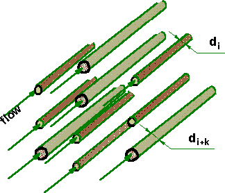
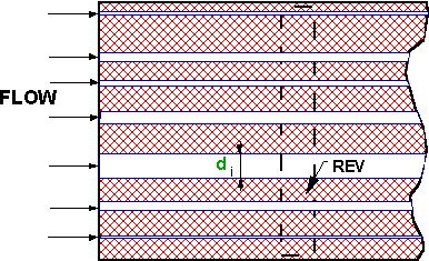
(25)A few useful illustrating figures given below. The morphologies were used in our studies.

Figure 1d. Approximate zones of flow regimes in porous media (Modified after Fand et al.1987)


Figure 1. Capillary morphology model of porous medium: a bundle of parallel pores embedded in solid

Figure 2b. Fissure closure morphology model: a bundle of parallel slits, all of width h, embedded in a solid